


Moving Coil Analog Geophone
Core Equipment Moving coil geophone main unit Multiple geophones connected in series (to improve signal clarity) Seismic recording station and main control unit
Key Technologies Electromagnetic induction technology (converts vibration into electrical signals) Inertial structure design (ensures accurate signal reception) Spike coupling (inserts firmly into the ground for reliable detection) Anti-interference, waterproof and dustproof technology
Product Introduction
Types and Characteristics of Equipment
Type
The 10Hz geophone is the most versatile, suitable for both shallow and deep formations, and has the largest usage volume in the Middle East and Africa (Tanzania).
Features
Simple structure, high reliability, drop-resistant, sand-wind resistant and stable under high and low temperatures.Passive operation without power supply, convenient for field construction.Low cost, good consistency, compatible with most seismic instruments worldwide.Analog signal output, directly connectable to the recording station without complicated configuration.Adaptable to harsh environments such as deserts, frozen ground, grasslands and swamps.

Moving Coil Analog Geophone
Converts seismic vibrations into electrical signals for exploration.

Moving Coil Analog Geophone
High-sensitivity sensor for geological and oil-gas surveying.
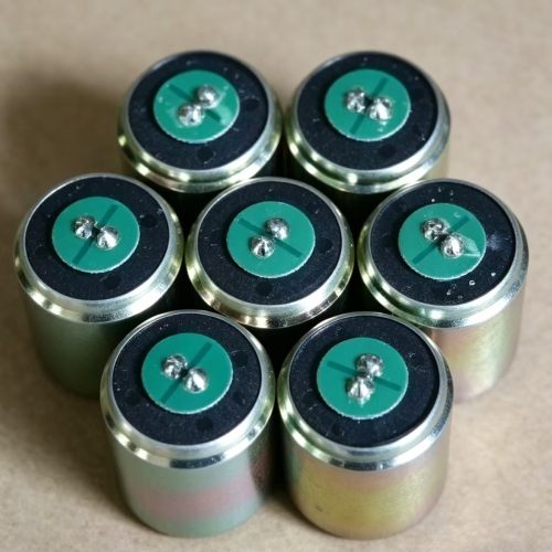
Moving Coil Analog Geophone
Core component of seismic data acquisition systems.
Basic Principles and System Composition
Basic Working Principle
Moving coil geophone = velocity seismic sensor Inertia principleGround vibration → the geophone case moves along with the ground → the internal mass and coil remain relatively stationary due to inertia. Electromagnetic inductionThe coil moves relative to the magnetic field of the permanent magnet → cuts magnetic lines of force → generates induced electromotive force. Signal relationshipOutput voltage is proportional to ground vibration velocity (not displacement, nor acceleration — it is “velocity-type”). Final functionConverts mechanical energy of seismic waves from underground into analog electrical signals for recording by the seismic acquisition system.
Overall System Composition
Internal Structure of the Geophone Permanent magnet (generates magnetic field) Coil winding (induces voltage) Mass element (provides inertia) Spring elements (support and restoring force) Housing, base, and connection terminals Spike (ensures good coupling with the ground)
Basic Principles and System Composition
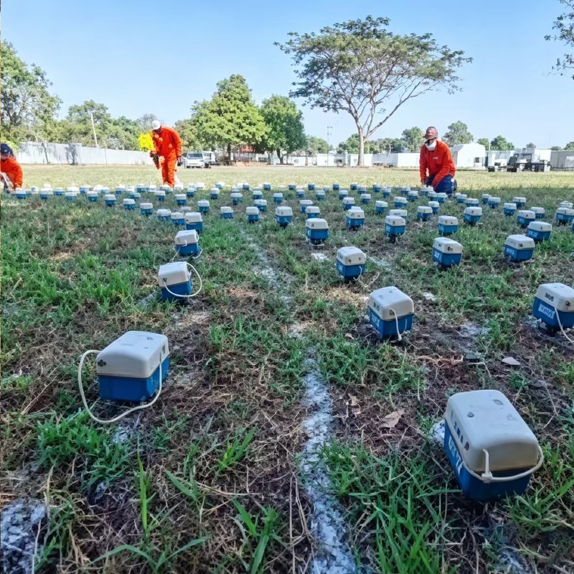
Line Layout and Positioning Deploy geophone points and shot points using GPS according to the design. Geophone Installation Bury or directly insert the spike into the ground to ensure tight coupling with the surface. Multiple geophones are connected in series to form a geophone array for improved signal quality. Cabling and System Testing Connect to the acquisition cable → link to the recording station → test continuity and noise level. Source Activation Vibroseis sweeping / explosive detonation to generate seismic waves propagating downward. Signal Reception and Recording Seismic waves reflect back to the surface → geophone vibrates → outputs analog electrical signals → amplified by the recording station → recorded by the host unit. Quality Control (QC) Review single-shot records to verify normal signal-to-noise ratio; repeat the operation if abnormal. Relocation and Recovery After completing one segment, retrieve geophones and cables, move to the next spread and repeat operations. Subsequent Data ProcessingRaw data → Preprocessing → Stacking → Migration imaging → Geological interpretation.
Related products

Multilingual Support
Multilingual professional foreign trade support

One-stop Logistics
Full logistics, customs clearance & shipping arrangement.

Complete Export Docs
Complete export documentation: inspection reports,etc.

On-time delivery excellence
Guaranteed punctual delivery via efficient production & logistics management.

After-sales & Tech Support
Timely after-sales & technical support for overseas clients.